UART
What is UART ?
A UART, also known as a Universal Asynchronous Receiver/Transmitter, is a semiconductor device programmed to oversee the connection between a computer and its serial peripherals. Its primary function is to facilitate communication between the computer and devices like modems.This enables the exchange of data between the computer and various serial devices.
How to Identify UART ?
UART Identification Method involves utilizing Digital Multimeter (DMM) tests to measure conductivity and voltage at specific pin outs on the board in order to identify the UART.
Description
This laboratory session aims to provide participants with foundational knowledge on the process of identifying UART pinouts and pin designations on a circuit board. This will be achieved by employing Digital Multimeter (DMM) measurements to analyze the voltage levels present at various points on the board.
Steps:
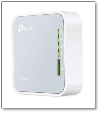
1. Utilize the appropriate tools to open the TP-Link AC750 Mbps Wireless Portable Mini Travel router (TL-WR902AC).
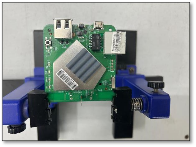
2. Perform a visual inspection of the Printed Circuit Board (PCB) to identify potential UART ports, typically characterized by a series of four or more pins.
3. Employ a Digital Multimeter (DMM) to systematically test each pin for identification, beginning with Ground (GND), Voltage supply (Vcc), Transmit (Tx), and Receive (Rx).
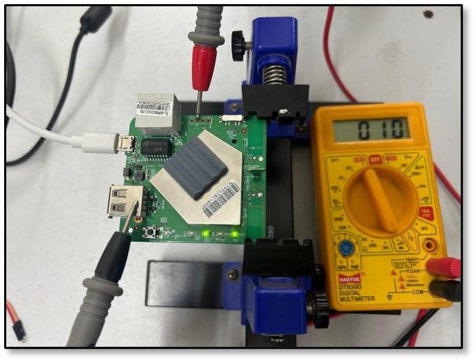
4. To confirm the presence of Ground (GND), follow the subsequent procedure. [Note: Hereafter, Ground will be referred to as GND]
a) Utilize the Digital Multimeter's continuity test function to ascertain connectivity.
 -->
-->
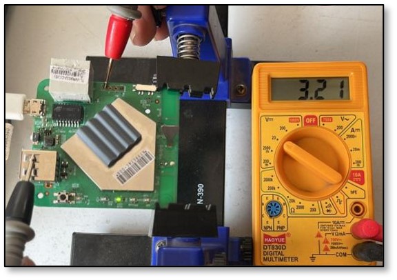
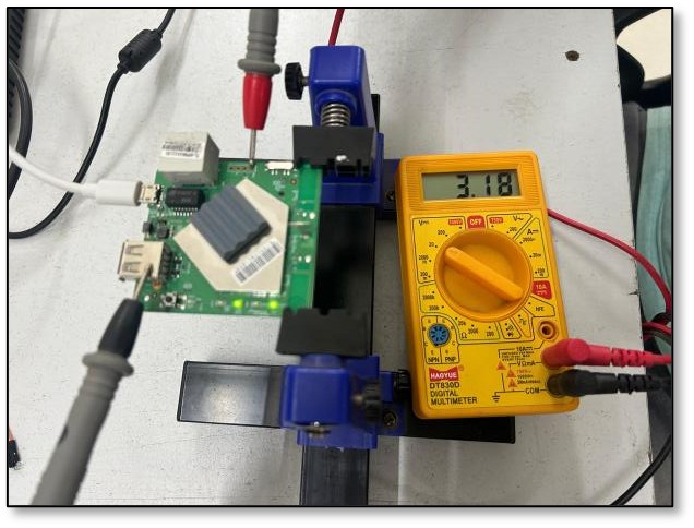
5. To confirm the presence of VCC (Voltage Common Collector), follow the subsequent procedure.
NOTE: Vcc is not used when connecting to serial interface, but identifying it helps in narrowing our search for Tx and Rx
- Power on the device.
- Multimeter Voltage test.
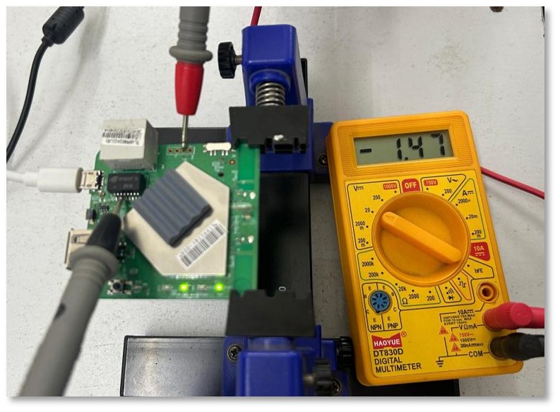
6. To confirm the presence of Transmit (Tx) pin, follow the subsequent procedure.
7. To confirm the presence of Receiver(Rx) pin, follow the subsequent procedure.
Identifying the Receive (Rx) pin can be a bit tricky since it doesn't have obvious traits.
Here's what to do:
Utilizing UART for Device Shell Access
Objective:
The objective is to establish access to the device shell through UART pins and subsequently locate credentials stored within the file system.
Description:
This laboratory session involves accessing the UART pins on the TP-Link AC750 Mbps Wireless Portable Mini Travel router (TL-WR902AC) utilizing a USB-TTL interface, with the aim of locating credentials within the file system.
Steps:
1. Establishing connection between identified UART pinouts and USB to TTL converter:
- Use wires and breakaway headers to connect the USB-TTL converter with the UART pins on the board.
- Solder wires or headers if necessary.
- Connect USB-TTL Tx to UART Rx pin on the board.
- Connect USB-TTL Rx to UART Tx pin on the board.
- Connect USB-TTL GND to GND pin on the board.
- NOTE: DO NOT connect Vcc.
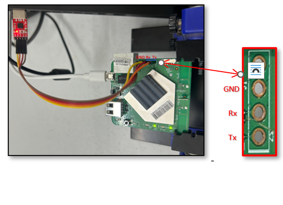
NOTE: The illustration depicts connections between a DIVA board and USB-TTL; similar connections can be established between an TP-Link AC750 Mbps Wireless Portable Mini Travel router (TL-WR902AC) and USB-TTL.
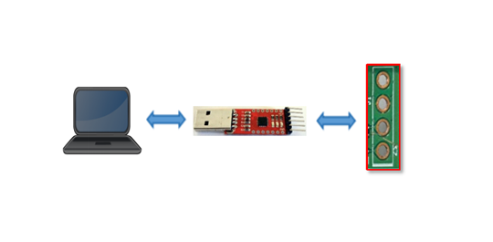
2. Shell Access:
- Once the physical connections are established, connect the USB-TTL to the USB port of your laptop.
- Access the port through the path /dev/ttyUSB0.
- Power on the device and promptly initiate a serial console utility.
- Available utilities for serial console access include:
- Picocom
- Screen
- Command: sudo picocom -b
-D
3. Baudrate Identification:
- The default baudrate for most devices is typically set to 115200.
- If binary garbage data is observed, it is highly probable that the specified baudrate is incorrect.

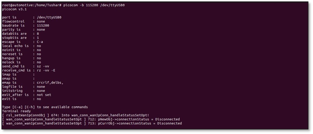
4. Upon observing log messages appearing on the screen, shell access is established provided that the wires are properly connected. Input any command, such as "ls", to verify functionality.
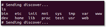
5. Identify and extract any significant credentials from the filesystem.
6. NOTE: In the event of encountering numerous "sending discover" messages.
7. These messages can be disruptive while operating within the shell; terminate the processes generating the messages if desired.